Choose Quality and Reliability with ChemTec Flow Meters and Excess Flow Valves
Authorized Distributor of ChemTec Products for Over 30 Years
As a proud authorized distributor of ChemTec products, FLW has provided a complete line of flow meters, monitors, and valves for over 30 years. Our expert technical support team is always available to answer any difficult application questions. Plus, as an authorized distributor, we can offer our valued customers volume, OEM, and reseller discounts.
Specialists in Low-Flow Technology
See Why ChemTec Leads the Industry
ChemTec specializes in low-flow liquid and gas meters, monitors, excess flow valves, and various materials and ranges. FLW has the perfect ChemTec meter or valve for your specific application. FLW ChemTec also offers custom and non-stock units in any volume, tailored to fit your needs. ChemTec products are engineered and manufactured in our factory from raw materials, ensuring the highest quality and reliability.
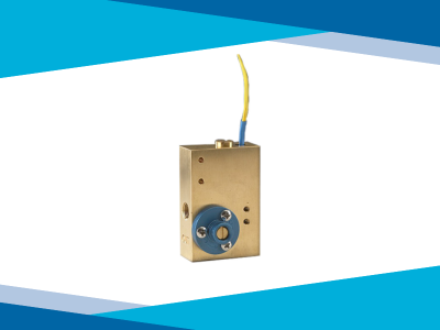
Flow Monitors & Switches
ChemTec's adjustable flow monitors, sensors, and switches are versatile and reliable tools for monitoring and controlling fluid flow in various applications requiring precision and durability. Critical applications include analyzers, welding systems, purge gases, and wet stations.
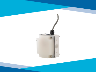
Flow Meters
ChemTec has a range of flow meters, including the MAO 500 Series and the MAO 125/250 Series, tailored to meet different industrial requirements. Their Flow Meters stand out for their customizability, quality, versatility, variety of material options, and low maintenance requirements.
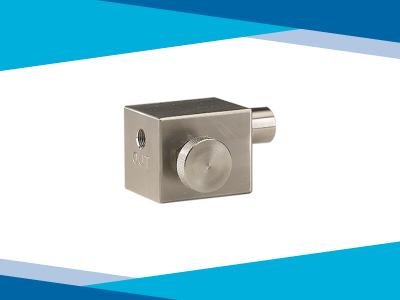
Excess Flow Valves
ChemTec's Excess Flow Valves are significant for enhancing safety and efficiency in various industrial applications by controlling the flow of gases and liquids, especially in high-pressure or hazardous materials. Their customizable nature further adds to their utility across diverse industrial applications.